Designing the Base of a Gantry Machining Centre
How the layout of a gantry machine decides what its base must do: fixed or moving bridge, rail seats, cross beam deflection, segmenting a long bed and what to tell the fabricator.
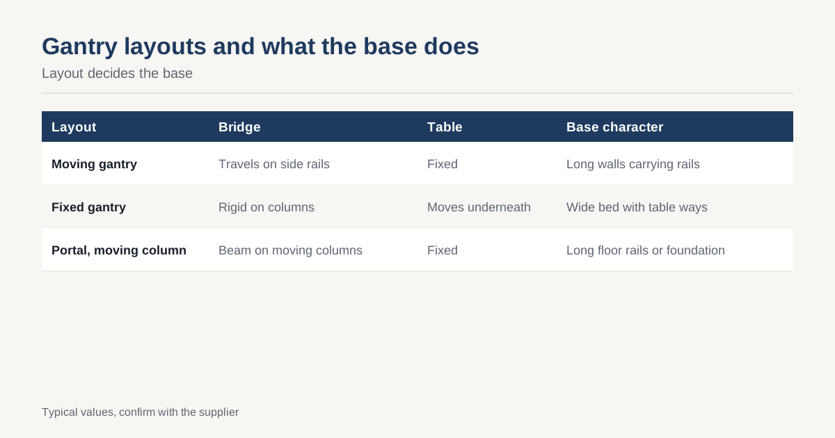
A gantry machine is a bridge on rails. A cross beam spans the work area, a carriage runs along it and the whole bridge either moves or stays still. The base carries the rails, supports the bridge and defines the geometry the machine will have for its working life. Layout decides the base, which is why the layout question comes first.
The main layouts
| Layout | Bridge | Table | Typical use | Base character |
|---|---|---|---|---|
| Moving gantry, fixed table | Moves along side rails | Fixed | Large, heavy or long parts | Long base with side rail walls |
| Fixed gantry, moving table | Rigid on columns | Moves under the bridge | Medium parts, higher accuracy | Wide bed with table ways |
| Portal with moving column | Cross beam fixed to moving columns | Fixed | Very large workpieces | Long floor rails or foundation |
On moving-gantry machines, the base is mostly a pair of long, stiff walls carrying rails, tied together by a deck or by the foundation. On fixed-gantry machines the base is a wide bed with the bridge columns bolted to it and the table ways running through. Their requirements differ, but both depend on stiffness and straightness of the rail seats.
The base as a reference line
Whatever the layout, the base provides a reference. The rails on it define the travel of the axis. An error in the straightness, flatness or parallelism of the rail seats becomes an error in the position of the spindle. The checks on the seats follow linear guide mounting surfaces: flatness per metre, parallelism between the two sides, and a reference edge.
Two features of a gantry base make that harder than for a smaller machine:
- Length. Seats may be many metres long, longer than a single grinding or milling setup.
- Span. The two rail walls must stay parallel across a wide gap, and any twist in the base appears as racking of the bridge.
The cross beam
The bridge beam spans between the two supports and carries the spindle carriage. Its stiffness is the main item in the machine’s accuracy budget. For a beam loaded at the centre and simply supported, the deflection grows with the cube of the span, so doubling the span makes the beam eight times more flexible for the same section. In real machines the ends are partly fixed by the columns, which reduces deflection, and the load position changes as the carriage moves.
Design implications:
- The beam should be a closed box with internal ribs, as in machine base rib design.
- Torsional stiffness matters as much as bending, because the carriage load sits off the beam’s axis.
- The worst case is the carriage at mid-span with the spindle at full extension.
- Weight on the beam is a cost, since it also loads the base through the columns and increases moving mass.
These points are developed in machine base stiffness and deflection.
How the base shares the load
The bridge’s weight and cutting forces flow down through the columns and into the base. For a moving bridge, the load moves along the rails, so each section of base is loaded as the bridge passes over it. The base walls must be stiff against the local load at every position, not only at one. That drives:
- Deep walls with internal ribs under the rails.
- Ties between the two walls at intervals, because a pair of free-standing walls can tilt towards each other under load.
- Attention to the foundation, which is part of the base. A gantry on a soft foundation will not hold line however stiff the steel is. See machine base levelling and grouting.
Acceleration and moving mass
A moving gantry accelerates a heavy bridge. The drive force acts at the rail, and the bridge’s centre of mass is above it, so there is a rocking moment each time it starts and stops. A twin-drive gantry with a drive on each side avoids twisting the bridge. The base must carry the drive reaction force, which means the motor mounts and rack or screw supports have to be built into the stiffest parts of the structure.
Natural frequency also matters. A heavy bridge on a long compliant base has a low natural frequency, and it can chatter during cutting. The relevant considerations are in machine tool natural frequency and chatter, and checking with finite element analysis helps, as in FEA for machine base design.
Making a long base
A long base can be made in one piece or in sections. The trade is covered in segmented versus monolithic machine bases, but for gantries the practical points are:
- Single piece: best for continuity of the rail seat, but limited by furnace size for stress relief, by mill travel and by transport.
- Sections: easier to make, treat and ship. The joint must be located with dowels or keys and bolted with a controlled preload, and the rail seats finished or checked after assembly.
- Foundation-supported: for very long machines the rails sit on grouted steel beams or concrete, and the base is an assembly of rail beams plus a table or frame.
Each choice shifts where the accuracy is made: in the fabrication shop, in the assembly or on the customer’s site.
Machining and inspection
Large seats need large machines and good measurement. A floor-type mill or a gantry mill cuts the seats, as in machining a machine base on a floor-type boring mill. Checks over many metres use laser methods, covered in laser tracker inspection of large machine bases, and the report should record method and temperature.
Transport
A gantry base is often among the largest parts a buyer ships. Length, width and weight set the transport mode and the route. A section that does not fit a standard container needs flat-rack or break-bulk shipping, which changes cost and lead time. The practical limits are in shipping heavy machine bases, and designers should check the shipping envelope before deciding on section sizes.
What to give a fabricator
A good RFQ for a gantry base includes:
- The layout type and the travel of each axis.
- The weight and centre of gravity of the bridge, carriage and spindle.
- The rail model, size and preload, with mounting dimensions.
- Flatness, straightness and parallelism targets for the seats, per metre and overall.
- The foundation concept: grouted, chocked or on anchors.
- Stress relief and machining sequence expectations.
- Section limits for transport, or a request for the fabricator to propose them.
- Inspection method and reporting format.
The machine base RFQ checklist lists these in order and shows what a fabricator needs to give a firm price.
Foundations and floor interaction
A gantry base rarely stands alone. On long machines the rails are carried by steel beams or a concrete foundation, and the foundation is part of the stiffness path. A soft or uneven floor lets the rail walls settle by different amounts, and the bridge then racks as it travels. Typical measures are a reinforced foundation designed for the machine’s static and moving loads, separated from the building slab by an isolation joint, and levelled with a documented procedure. The machine builder normally issues a foundation drawing with load points, pit dimensions and tolerance for flatness of the supporting surface.
The base fabricator needs this information early, because it decides where levelling pads and anchor points sit, and whether the base is designed to rest on a grouted bed or on discrete chocks. A base designed for chocks must be stiff enough to span between them, while a base on a full grout bed can be lighter. Asking the foundation question before the drawing is released avoids the common case where a good base is installed on a floor that cannot hold its line.
Closing checklist
- Decide the layout before the base.
- Check the cross beam at its worst load position.
- Tie rail walls together to prevent tilt and racking.
- Locate drive reactions in stiff parts of the structure.
- Plan the sectioning and joints early.
- Specify rail seat tolerances per metre and overall.
- Check the shipping envelope.
To have a gantry base quoted as a single structure or in sections, send the drawing through the RFQ page. We respond within 24 business hours. For background see the Wikipedia article on machine tools.
Common questions
What is the difference between a moving gantry and a fixed gantry?
On a moving gantry the bridge travels along rails on the sides of a fixed table, so the workpiece does not move and the base must be long enough for the bridge travel. On a fixed gantry the bridge is rigid on its columns and the table moves beneath it. Moving gantries suit very heavy or large parts; fixed bridges are stiffer and usually more accurate for medium sizes.
Why does cross beam deflection change along the span?
Because a loaded beam deflects most in the middle. When the spindle carriage sits at the centre of the bridge, the beam is at its most flexible, and when it moves toward a column it is stiffer. The error therefore depends on carriage position, and a good design checks stiffness at the worst position, not only at the ends.
Can a long gantry base be made in sections?
Yes, and many are, because a single long fabrication is hard to machine, treat and ship. Sections are bolted and doweled together and the rail seats are finish machined or aligned after assembly. The joint then becomes part of the accuracy budget, so the design must address how the sections are located and how the rails are made continuous.
Have a base to price? Send the drawing and we match it to up to three fabricators in Vietnam. Free for buyers, answer within 24 business hours.