Injection Moulding Machine Beds: Platen Loads and Base Design
What the bed of an injection moulding machine carries, how clamp force stays in the tie bars, how mould weight bends the bed and what to specify for a welded frame with oil tank.
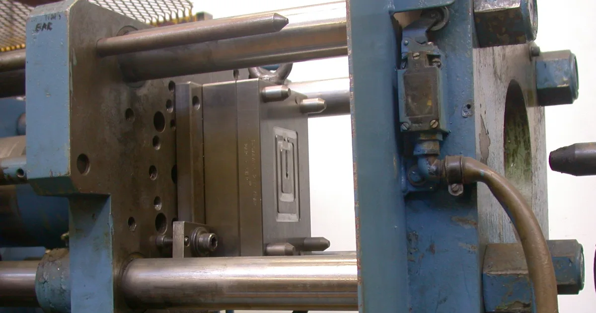
An injection moulding machine looks like a long horizontal bench with two ends: the clamping unit with its mould on one side, the injection unit on the other. Under all of it sits a bed, usually a welded steel frame. The bed does less than people expect, which makes it easy to over-design in some places and under-design in others.
The machine in outline
A moulding machine has three main parts.
- The clamping unit. A fixed platen, a moving platen and tie bars, usually four, hold the mould shut against the injection pressure. A toggle linkage or a hydraulic cylinder moves the platen.
- The injection unit. A screw in a heated barrel melts the plastic and pushes it into the mould.
- The drive and control. A hydraulic power pack, or electric servo drives, plus the controls.
The size of a machine is given by its clamping force, in kilonewtons or tonnes. Machines run from a few tens of tonnes to several thousand. The base grows with them.
Where the clamp force goes
The clamping force is a closed loop. The injection pressure pushes the mould halves apart, the platens carry that force to the tie bars, and the tie bars hold the platens together. The force passes through steel and returns, without entering the bed.
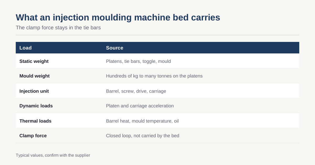
This fact is central to bed design. The base does not need to resist clamp force. Its loads are:
| Load | Source |
|---|---|
| Static weight | Platens, tie bars, toggle, mould |
| Mould weight | Hundreds of kilograms to many tonnes, hung on the moving platen and on the fixed platen |
| Injection unit weight | Barrel, screw, drive, hopper, and its carriage |
| Dynamic loads | Platen acceleration and stopping, injection unit movement |
| Thermal loads | Barrel heat, mould temperature, hydraulic oil |
Those loads are mostly vertical and modest compared with those on a machine tool.
Why stiffness still counts
A bed that sags changes the alignment of the clamping unit. The usual consequences are:
- Platen parallelism. The moving platen runs on guide rails or slide pads on the bed. If the bed bends under mould weight, the platen tilts, and the two halves of the mould meet at an angle. The result is flash at one corner and uneven wear on the mould.
- Tie bar loading. Uneven closing loads the four tie bars differently, which shortens life and distorts measurements of clamp force.
- Nozzle alignment. The injection unit must line up with the sprue bush. A bed that twists offsets it, causing leakage at the nozzle.
For these reasons the bed has to stay straight and level over its length, with a deflection limit tied to the mould weight. Machine base stiffness and deflection gives the method for setting a limit from a load case.
What the bed looks like
The usual bed is a welded box frame of plate, with internal ribbing under the platen supports and under the injection unit. Features include:
- Mounting pads for the fixed platen, the guide rails and the injection unit carriage.
- Pockets for the hydraulic power pack, valves and electrical cabinet.
- An oil reservoir, on hydraulic machines, formed from part of the bed.
- Leveling feet or pads with pockets for anti-vibration mounts.
- Forklift or crane points for moving the machine.
Layout follows the principles in machine base rib design: depth where bending is, ribs under concentrated loads and triangulation where twist may occur.
The bed as oil tank
Using the bed as the oil reservoir saves a separate tank, but adds requirements.
- Leak-tight welds. Continuous seal welds on every seam that touches oil, and a leak test, commonly with air pressure and soap solution or a fill test.
- Baffles and sloped floor so that oil settles and drains fully.
- Cleanout access so the interior can be cleaned.
- Interior coating resistant to hydraulic oil, or bare steel treated for oil service, cleaned of weld spatter and scale. See shot blasting and priming a machine base for blasting and coating of enclosed spaces.
- Oil temperature. The tank also dissipates heat, so area and layout matter.
A tank must be clean. Weld spatter, slag or blasting grit left inside ends up in valves and pumps. The specification should require cleaning and a flush before delivery.
Distortion and machining
The bed supports precision features: guide rail seats, platen mounting faces and the injection unit rails. These need flat, parallel surfaces over several metres. The usual route is welded frame, stress relief, then machining on a large mill, as in machining a machine base on a floor-type boring mill. Stress relief and distortion control apply as for any large fabrication, covered in welding distortion control and stress relief and flatness.
Typical tolerances needed are flatness and parallelism of the rail seats, and alignment between the fixed platen face and the injection unit axis. They should be set from the machine builder’s design and shown in GD&T terms. See GD&T for machine bases.
Thermal considerations
The barrel runs hot, typically a few hundred degrees Celsius at the nozzle for common plastics, and the mould is held at a set temperature by water or oil. Heat travels into the bed through the injection unit and platens. Practical rules:
- Insulate or shield the bed from the barrel.
- Keep the oil cooler away from the main structure.
- Leave expansion room where the injection unit carriage slides on the bed.
- Do not rely on a perfectly steady temperature. A bed that tolerates a few degrees of variation is more forgiving.
Safety and standards
Moulding machines are subject to machinery safety standards. In Europe, EN 201 covers injection moulding machines, and the CE marking process applies at the machine builder level. The bed fabricator is not responsible for it but should supply drawings and weld records that the builder needs. For documents that follow a shipment, see export documents for machinery.
What to put in an RFQ
- Machine size, clamping force and the maximum mould weight.
- Loads and mounting points for each unit.
- Rail seat tolerances and the datum scheme.
- Whether the bed doubles as an oil reservoir, and its volume.
- Leak test requirements and interior cleanliness.
- Paint specification, inside and out.
- Levelling method and foundation or mount type, per machine base levelling and grouting.
- Lifting points and shipping constraints.
Interfaces to the rest of the machine
The bed carries a number of assemblies built by other suppliers: the platens from a foundry, the injection unit from a specialist, the hydraulic or electric drive and the control cabinet. Each arrives with its own mounting pattern. The fabricator’s drawing therefore needs a datum scheme that ties all these patterns together, not just the pattern of each rail seat on its own. A common method is to measure everything from a single machined reference face and a pair of dowel holes near one end of the bed, so that assembly in the machine builder’s plant can be repeated and checked.
Cable and pipe routes are another interface. Openings in the bed for hoses, wires and oil lines should be placed during design, with edges deburred and protected, because cutting holes after painting damages the coating and can distort the frame. Ask the fabricator for a fit check with a template or a jig, so that a mismatch is found in the weld shop and not on the assembly line.
Checklist
- Treat the bed as a weight-carrying frame, not as a clamp-force structure.
- Set a deflection limit from the mould weight.
- Keep rail seats flat and parallel to the stated figures.
- If it is a tank, specify weld sealing, test and cleaning.
- Plan for thermal separation from the barrel.
- Supply the design loads and tolerances in the RFQ.
To have a moulding machine bed quoted with or without an integral tank, send the drawing through the RFQ page. We respond within 24 business hours. For background see the Wikipedia article on injection moulding machines.
Common questions
Does the machine bed carry the clamp force?
No. The clamping force is a closed loop through the platens and tie bars, so it stays inside the clamping unit and does not pass into the bed. The bed carries weight: the platens, the mould, the injection unit, the hydraulic or electric drives and any oil. Its job is to hold the clamping unit straight and level, not to resist the clamp force.
Why does bed stiffness still matter?
Because a bed that bends under the weight of a heavy mould tilts the moving platen relative to the fixed platen, and the mould halves meet unevenly. Parallelism of the platens affects flash, mould wear and tie bar loading. A stiff bed also keeps the injection unit aligned with the nozzle seat so material does not leak.
Can the bed double as an oil tank?
Many hydraulic machines use the bed or part of it as the oil reservoir, which saves cost and space. It then needs sealed welds, drains, baffles and an interior coating that resists oil, and it must be tested for leaks. Machines with electric drives have no tank and a simpler bed.
Have a base to price? Send the drawing and we match it to up to three fabricators in Vietnam. Free for buyers, answer within 24 business hours.