Fabricating Hydraulic Press Frames: Fatigue and Deflection
How welded hydraulic press frames are designed for deflection and fatigue, why weld detail matters more than steel grade, and what thick-plate fabrication needs from a shop.
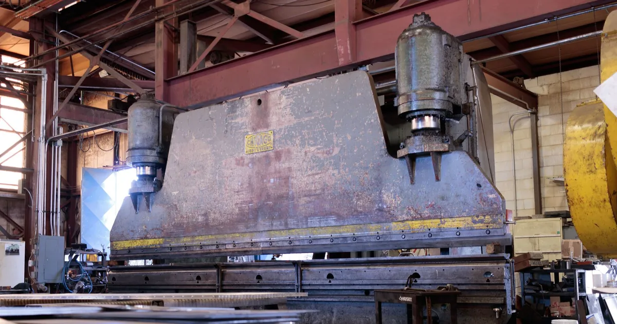
A hydraulic press frame carries the full force of the press, cycle after cycle, for years. It is a structure where fatigue cracks, not sudden overload, are the usual failure. It is also a machine element whose stiffness affects every part it makes. Fabricating a frame well is mostly about knowing which of these two concerns governs each region, and where the welds sit.
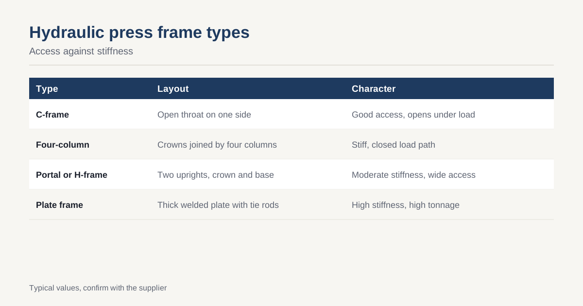
Frame types
| Type | Layout | Typical use | Character |
|---|---|---|---|
| C-frame (gap frame) | One-sided open throat | Small and medium presses, straightening, assembly | Good access, opens under load |
| Four-column | Top and bottom crowns joined by four columns | Moulding, forming, deep drawing | Stiff, closed load path, good for large bolsters |
| Portal or H-frame | Two uprights with crown and base | Workshop presses, straightening, bending | Moderate stiffness, wide access |
| Plate frame | Welded plate sides with tie rods | Heavy forming, high tonnage | Thick plate, high stiffness |
Each type is a compromise between access, stiffness and cost. A buyer who knows the part and process can often narrow the choice quickly.
What deflection does
Under load, the frame stretches, bends and tilts. A C-frame throat opens and the ram tilts relative to the bolster. A four-column frame stretches along its columns and the crown and bolster bend between them. Consequences include:
- Stroke error, because the position of the bottom of the stroke changes with force.
- Tilt of the ram, causing uneven pressing, one-sided wear and out-of-flat parts.
- Bolster bending, which affects the part and the die.
The press builder sets deflection limits from the part tolerance and the die. Typical limits are expressed as a deflection per metre of bolster length under full load, often some tenths of a millimetre, and angular tilt of the ram, but the right figures depend on the process. The fabricator needs them as numbers on the drawing, not as words. Method for setting them is the same as in machine base stiffness and deflection, and FEA for machine base design covers how to check them.
Fatigue in welded frames
A press cycles through high load many times. Tens of thousands of cycles a year are common in production presses, so over ten years a frame sees hundreds of thousands. Fatigue is therefore the central strength question.
Three points matter in design:
- Stress range, not peak stress. Fatigue damage depends on how much the stress varies in each cycle. A press that loads and unloads fully has a range equal to its working stress.
- Weld detail. The fatigue strength of a welded joint is set by its geometry: the notch at the weld toe, the root, any misalignment. Design codes give fatigue classes by detail. See Eurocode 3 part 1-9 or the recommendations of the International Institute of Welding.
- Weld quality. Undercut, porosity, lack of fusion and cracks cut life.
Design codes assign the same fatigue class to a given detail in different structural steel grades. A frame in S355 therefore has no better fatigue life than the same detail in S275. The comparison is made in S355 versus S275, and the US equivalent is in A36 versus A572 Grade 50.
Details that improve fatigue life
- Full-penetration welds at critical joints, in place of fillet welds, where the load passes through the joint.
- Smooth weld profiles, with the toe ground or blended in the highest-stress regions.
- Generous radii at corners and around openings, with the inside edges ground smooth.
- Avoid sharp changes of section and stiffness that concentrate stress.
- Avoid welds in the highest-stress regions where possible, by shaping the plate or using a casting or forging for the critical node.
- Stagger welds and avoid intersections of several welds at one point.
Where part of the frame is a casting or a forging, the weld joins it to plate away from the peak stress, not at the point where stress is greatest.
Thick plate fabrication
Press frames use thick plate, often from 30 mm to 100 mm or more. Welding such plate brings specific risks.
- Hydrogen cracking in the heat-affected zone, controlled by preheat, low-hydrogen consumables and controlled interpass temperature.
- Lamellar tearing, where plate is stressed through its thickness. Plate with improved through-thickness properties, designated Z25 or Z35 under EN 10164, is specified for joints loaded that way.
- Distortion and residual stress, larger in thick sections. See welding distortion control.
- Heat input and cooling rate, which control toughness in the heat-affected zone.
Welding procedures must be qualified for the grade and thickness, as covered in ISO 3834 for Vietnamese fabricators. A fabricator without experience in thick plate should be asked for procedure qualification records and for a similar reference job.
Stress relief and machining
Thick welded frames hold high residual stress, and stress relief is almost always specified. The part is heated in a furnace to a controlled temperature, held and cooled slowly, then machined. Furnace size limits frame size, so large frames are often built in sections. The sequence and the reasoning are in machine base stress relief and flatness and segmented versus monolithic machine bases.
The faces that matter, such as the bolster seat, the ram guides and the crown mounting, are machined after relief, on a large mill as in machining a machine base on a floor-type boring mill.
Inspection
For a frame with fatigue duty, weld inspection is more than a visual check.
| Method | Finds | Typical coverage |
|---|---|---|
| Visual | Profile, undercut, surface defects | All welds |
| Magnetic particle or dye penetrant | Surface cracks | Critical welds, toes and corners |
| Ultrasonic | Internal flaws, lack of fusion | Full-penetration welds |
| Radiography | Internal flaws | Where specified |
The scope should be on the drawing or in the inspection plan, per inspection test plans for machine bases. Safety requirements for hydraulic presses in Europe come from EN 693, applied at machine level.
Drawing information a fabricator needs
- Press force, stroke and duty cycle, including expected number of cycles.
- Load cases and eccentric loading.
- Allowable deflection and tilt.
- Plate grades, thicknesses and through-thickness quality.
- Weld symbols with joint type, size and inspection level.
- Fatigue-critical details marked on the drawing.
- Stress relief, machining and tolerance requirements.
- Painting and surface protection.
Load cases that catch designers out
Two load cases are often missed in a first press design. The first is off-centre loading. A die rarely sits exactly under the ram, and a part pressed to one side puts a bending moment into the crown and columns that the central-load calculation does not show. Press standards and builders specify an eccentricity, often a fraction of the bolster width, that the frame must carry with deflection and tilt within limits. The second is the return and decompression phase. When the pressure is released, the stored elastic energy in the frame is let go, and some presses produce a sharp load reversal that adds to fatigue cycles.
Both cases should be on the drawing or in the specification sent to the fabricator, along with the number of cycles expected per year. A fabricator who knows only the nominal force cannot judge which welds need full penetration or grinding, and may price and build every joint the same.
Checklist
- Identify the governing check in each region: fatigue or deflection.
- Choose the frame type for access and stiffness.
- Use full-penetration welds and ground toes at critical joints.
- Specify Z-quality plate for through-thickness loading.
- Require qualified welding procedures for thick plate.
- Stress relieve before machining.
- Define inspection scope in the plan.
To have a press frame quoted with the weld and inspection details you specify, send the drawing through the RFQ page. We respond within 24 business hours. For background see the Wikipedia article on hydraulic presses.
Common questions
What limits a press frame, strength or stiffness?
Both, in different places. Stress governs the thick welded joints and the areas around openings, because a frame sees repeated high loads and can crack through fatigue. Stiffness governs the accuracy of the parts pressed, because frame stretch and tilt change the stroke and the parallelism between ram and bolster. A good design checks both and does not trust the stress result alone.
Does higher-strength steel improve fatigue life?
Not for welded joints. Fatigue life of a weld depends on the geometry of the detail, the stress range and the weld quality, and design codes assign the same fatigue class to a given weld detail across common structural grades. Better details, full-penetration welds, ground weld toes and inspection raise fatigue life, not a higher yield grade.
Which frame type is stiffest?
Closed frames, such as four-column and portal types, are stiffer than open C-frames because the load loops through a closed structure. A C-frame opens at the throat under load, which tilts the ram relative to the bolster. C-frames suit small and medium presses where access from three sides matters; larger forces and tighter accuracy move designs toward closed frames.
Have a base to price? Send the drawing and we match it to up to three fabricators in Vietnam. Free for buyers, answer within 24 business hours.